I’ve recently finished replacing the wiring harness on my P5B Coupe with a ‘New Old Stock’ harness, so it seems a good time to cover this in some detail in an article. I also plan to write a series of articles explaining how each of the main circuits of the Rover P5 electrical system works, but that’s for the (near) future.
Why???
Before we begin, it’s worth mentioning why I took this drastic step. My car, like many classics of the period, had numerous places where the insulation on the old harness was fraying and cracked. This is obviously a fire hazard and needed repairing. My original plan was to re-terminate wires and/or splice-in new sections. That would be the simplest thing, and if done properly would have been fine.
Period car wiring looms were often a mixture of braided cable and more modern PVC wire, and the P5B is like this. The braided cable is braided over a PVC inner, so although the braiding may be frayed it isn’t necessarily electrically unsafe. Obviously if the braiding and the PVC are cracked then that is dangerous. But there was so much fraying on the loom in my car it would have basically needed every wire re-terminating and / or splicing.


To add to this, my car had suffered a small engine fire a few years before I bought it. The fire had damaged the engine wiring and a few ancillaries, but had been extinguished before doing too much damage. The repairers had cut the old harness at the 4 places it passes through the firewall, and connected parts of another harness in the engine bay.
Unfortunately not only had they used the wrong harness from a different model with different wire colours (and hadn’t removed redundant wires, but left them dangling in the engine bay), but they spliced the two harnesses together using about 60 bullet connectors, which are not the most reliable electrical connectors. Again, I could have crimped and soldered these properly, or replaced the engine wiring with the correct wires, but the whole thing would have been a patchwork and a definite weak point.
There was also the related issue that the engine-bay was looking very tired and dirty, and there was a lot of surface-rust in places, so sorting that was important as well.
As I contemplated my options, a New Old Stock (NOS) harness for a P5B Coupe popped-up on eBay. I also could have ordered a new harness from Autosparks, but the eBay harness was ¼ of the price, so I ordered it. This could have been a mistake, as old wiring will still degrade with age even if not fitted to a car, but when it arrived the harness was almost as new. It was slightly the wrong year, so a couple of wires were wrong, but as I wanted to fit some additional components anyway, I could easily fix this. I’d then have a period-correct harness, adapted to exactly how I want it.
I’ll talk more about how I adapted the harness a little later.
Recommended Reading
Whilst re-wiring my car and researching this topic I’ve found the following book invaluable, and thoroughly recommend you obtain a copy:
Wiring Diagram
A good wiring diagram is an absolute necessity. The diagram in the Workshop manual is quite poor as it’s small, has errors and isn’t in colour. There is a free PDF available from the Rover P5 Club for members, but as I wanted to make some changes I decided to create my own full-colour circuit diagrams of the complete P5B electrical system. This was rather time-consuming, but invaluable in understanding the wiring and planning the changes I wanted.
The overall layout I used is somewhat similar to the free PDF version as that seems the most logical layout, so thanks are due for inspiration to the Club Member who created that version. My version is quite different in detail, and has lots of additional information as well. It’s 3-pages in total, and is correct for a 1968 P5B (both Saloon and Coupe), although Rover sometimes made running changes, so I can’t guarantee everything is correct for your car.
To make things easier, I’ve had the standard version of my diagram professionally printed at A3 size, and these are available to buy in the website Shop and also below here, in full colour, both on plain-paper and also laminated. A3 is a great size as there is so much information packed-in, and they look really smart (I may be biased). The A3 laminated prints look great on the garage wall as well!
Recommended Tools and Consumables
In order to work on Rover P5 and P5B electrics to a standard similar to original, whether replacing the harness or re-terminating a wire, there are a few general tools you’ll need, plus a few specialised tools that I strongly recommend you buy – they will transform the quality of the final result.
General Tools
- Wire Cutters
- Wire Strippers
- Knife
- Soldering Iron (I tend to use a propane gas iron, which saves the need for a power connection, but that’s a personal preference. Any soldering iron of about 30W upwards should be fine).
Specialised Tools
Multi-Meter
I recommend a pen-type meter, as they allow you to see the display next to where you’re probing – much less chance of the probe slipping as you turn to look at the display. You want a meter with at least D.C. voltage measurement and an audible continuity check. I bought this one – I recommend it: https://amzn.to/2BhmYvR
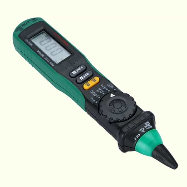
It’s also very useful if the lead is extra-long (I’d suggest 3 metres), with a clip rather than a probe. This allows you, for example, to clip the meter to a wire in the engine bay, then take the meter inside the car to probe for continuity behind the dashboard. I made my own using a crocodile clip, some flexible wire and 4mm banana plug.
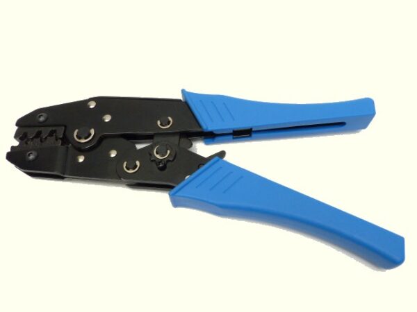
Lucar-type Crimp Tool
You can get cheap crimping tools, but often the jaws don’t align properly and the quality of the crimp will be poor. I recommend this one – the crimped connectors look as good as the factory:
http://www.vehicle-wiring-products.eu/product.php/269/ratchet-crimping-tool
Bullet Crimp Tool
These aren’t as widely available as the above, but they are vital and well worth buying if you’re doing any work on a Rover P5 or P5B electrical system, which uses a great may Bullet connectors:
http://www.vehicle-wiring-products.eu/product.php/272/bullet-crimping-tool

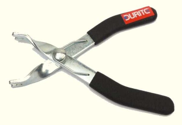
Bullet Closing Tool
These aren’t essential, but they do make inserting bullet connectors into connection blocks much easier, especially in confined areas, and you won’t damage the crimp or the cable (which pushing on the cable often does):
http://www.vehicle-wiring-products.eu/product.php/336/bullet-closing-tool
Consumables
I recommend buying a selection of ‘Lucar’ (6.3mm) crimp connectors and Bullet crimp connectors for different wire sizes. These come either plain brass and tinned brass – tinned brass are probably the most durable. Don’t use the pre-insulated Lucar terminals – they look terrible and don’t crimp or support the wire insulation properly. Vehicle Wiring Products can supply the right ones.
I also recommend that if you need to replace any wiring, try to source the correct colour-coded wire of the same or larger conductor size. Vehicle Wiring Products supply every colour cable in PVC insulation, and Autosparks can supply the correct coloured braided cable. Most modern PVC cable is ‘thin-wall’ type so it takes-up less space in the harness – this is perfectly OK for classic cars as long as the conductor rating is correct.
You might also need a selection of bullet connector blocks. These are made for 1, 2, 3 and 5 cables. Just be aware that the 2 and 3 cable types are for connecting all 3 wires together – they aren’t multi-pole. The 5 cable version is multi-pole. Again, available from Vehicle Wiring Products and Autosparks.
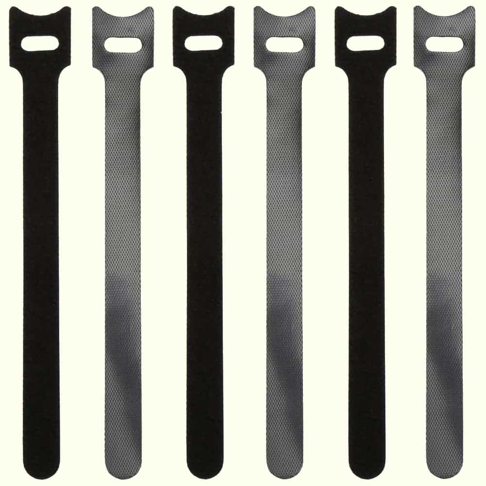
Re-usable ‘Velcro’ Cable Ties: These are really handy if you need to unwrap any of the harness to get to wires – you can keep the harness together using these, and can easily move and re-use them as needed. H&S 100 Reusable Cable Ties: https://amzn.to/2Df7iJJ
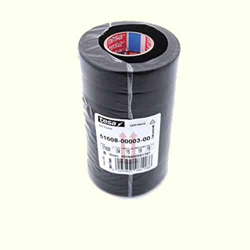
Harness Tape. Whatever you do, don’t use insulation tape to re-wrap the harness! The adhesive degrades rapidly and you end-up with a horrible, sticky mess. You should use proper harness tape that doesn’t have any adhesive and can be removed easily if needed. I recommend Tesa H5160803 Wiring Harness Harness Tape 19 mm x 15 m Roll: https://amzn.to/2D8aPtA
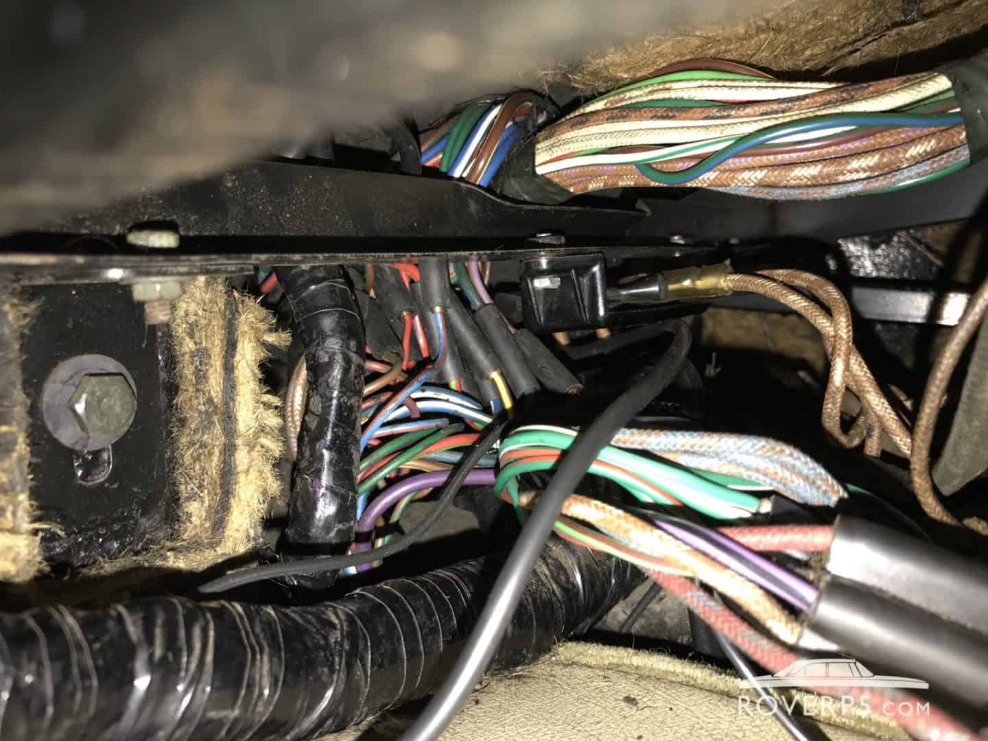
The P5 Wiring Harness
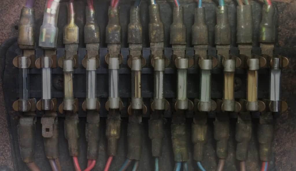
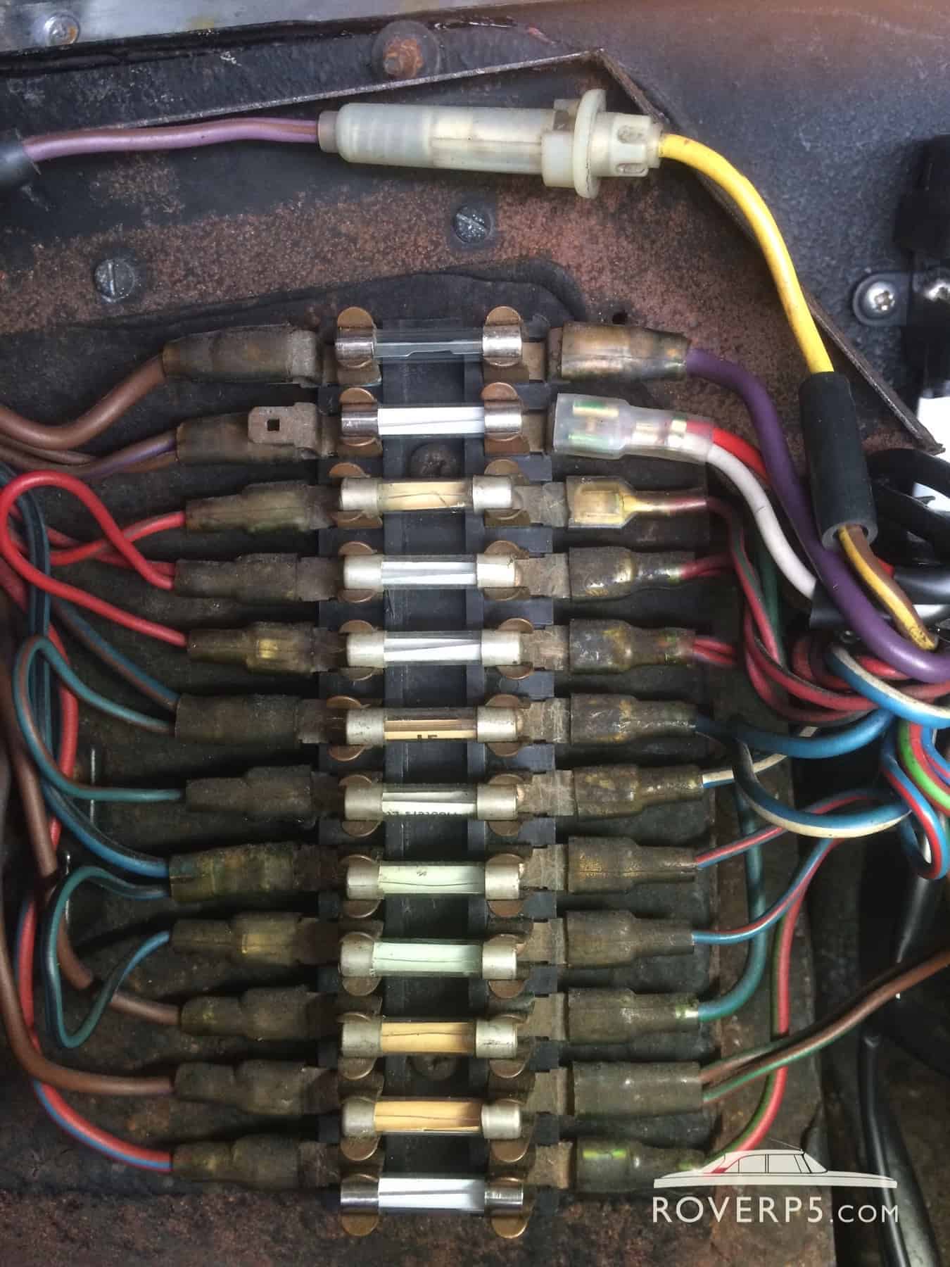
Over the years numerous changes occurred to the P5 wiring and electrical components – too many to list. The number of fuses and general complexity increased significantly over time, culminating with the P5B. Most changes happened at the major model changeovers between Mark I / IA / II / III / P5B, but between these there were lots of running changes, not all documented in the Workshop Manual.
This series of articles focuses on an early P5B from 1968 with a ballasted coil and an alternator rather than dynamo, but earlier and later P5B’s are broadly similar with only relatively minor incremental changes each year.
By far the biggest change to be aware of was the change from positive to negative earth in 1965 – its really important you know whether your P5 is positive or negative earth. P5B’s are simple in this regard – all were negative earth, and all P5B’s used an alternator, not a dynamo.
Most P5 and P5B harnesses seem to use a combination of braided wire and PVC-insulated wire. The braided wire was mainly used on the ‘supply’ side of the fusebox. Perhaps Rover used this as an extra layer of protection against wire damage on the unfused supply wires? I’m not sure as it seems like a significant complication, but Rover were very-much engineering-led at this time, so that may be the case. To maintain originality I recommend getting the correct braided wire from Autosparks if your car had this originally – little details like this are an interesting part of the cars history.
Crimp or Solder?
Terminals on the standard Rover harness were mainly both crimped and soldered, and that’s what I’d recommend if you replace any terminals. Crimping (done correctly) should give the best electrical connection, but there is a chance for water to get into the joint through capillary action. That will increase resistance over time. Soldering is watertight, but will normally have a slightly higher resistance than a crimped joint. Doing both is best – crimp first, then solder.
Replacing the Wiring Harness
Now, finally we can cover the process of replacing the harness.
Step 1: Label the New Harness
It may be tempting to jump-in and start ripping wires out of your car, but I strongly advise taking your time and doing Step 1 first. It makes fitting the new harness much easier and less error-prone. This is what I did, and at the same time I made a number of modifications to the harness (see later). My car started first-time after connecting the last wire of the harness – even I was surprised by that.
The main reason I recommend labelling the harness first is that if there are things you’re unsure of at this stage, either in the wiring diagram or new harness, you still have a functioning harness in your car that you can refer to. This can be invaluable, and save you a great deal of heartache later.
I worked through every wire in the harness checking against the wiring diagram, checking it with the continuity tester on my multimeter, and making sure the wire colour-code matched the diagram. Any discrepancies were noted on the diagram, and checked against my car. I found a couple of wires in the NOS harness that were different to the diagram – perhaps some of Rover’s undocumented running changes, or expediency by the harness supplier.
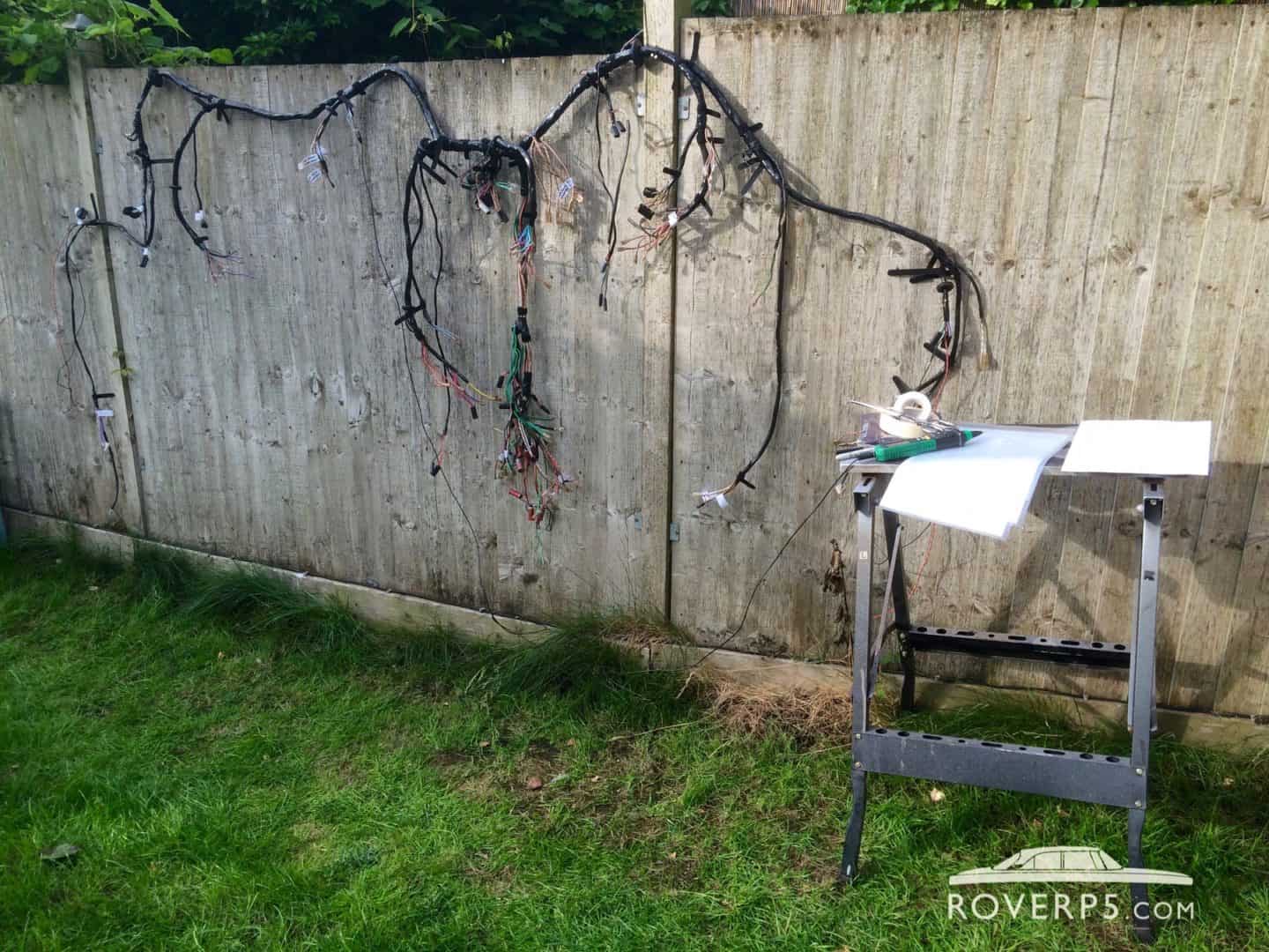
To make this easier, and since it was Summer, I hung the harness on nails hammered into the garden fence! Obviously any wall would do, although a fence makes this very easy. I hung the harness in the approximate layout it would sit in the car. This made things much easier, and I got a sun tan at the same time.
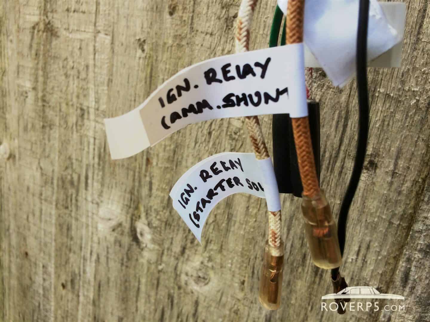
As I checked each wire, I labelled the end with a flag of PVC insulation tape. In permanent market I wrote the component it was connecting to with the terminal number if appropriate. Underneath that, in brackets, I wrote what was as the other end of the cable. So one of the tape tabs on a cable might look like this:
HEADLAMP MAIN LHS
(FUSEBOX F14)
At a glance I could then see this wire was to be connected to the Headlamp Main Beam on the left-hand-side (nearside). In case of problems, I can also see the other end connects to the Fusebox terminal 14. This made troubleshooting much easier, and once tested in the car I removed most of the flags (I left a few that were hidden – you never know if they may be useful in the future).
Not only does this step check your harness against the wiring digram, it makes re-connecting the harness quite simple and familiarises you with the harness itself. And you’re not upside down under the dashboard when doing this, but standing comfortably getting a suntan in your garden.
OK, I think this part is long enough. Here’s a video I’ve posted about the whole re-wiring – well worth a watch (and a subscribe!), and you’ll get a sneak-peak of what will be covered next.:
[embedyt] https://www.youtube.com/watch?v=_Qc4v9IWaCk[/embedyt]In Part 2 I’ll cover in some detail the process to actually replace the harness in a Rover P5B. This should be published on the website in a few days.

Trackbacks/Pingbacks