Rover P5B Coupe In The Nude [Part 4]: Front Bodywork
Let’s start the next chapter in the dismantling of a Rover P5 by Cyrille, who has kindly allowed the use of his images. Here Cyrille shows the dismantling of the front bodywork and removal of the subframe. The P5 body features numerous panels that can be simply unbolted. As mentioned in the Introduction, it’s interesting to compare the first images here (which don’t look too rotten) to some of the later photos of what lies beneath.
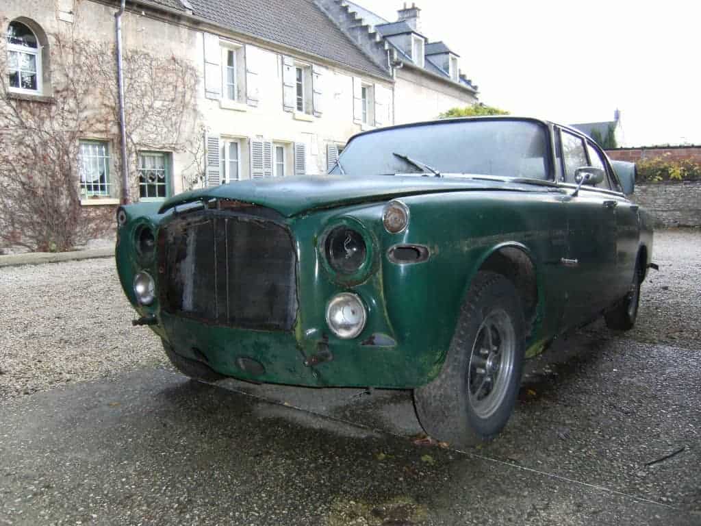
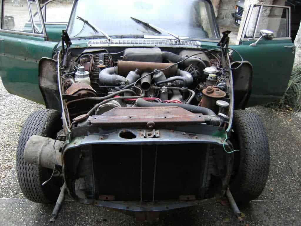
Here are a couple of photos of the front-end before dismantling begins:
And here’s the front with wings unbolted. Quite a transformation, and it’s interesting as it shows the state of body engineering in the late 1950’s: wings, although being integrated into the car from a styling viewpoint, were still very much an ‘add-on’ to the basic car structure. This wastes space around the wheel arches, although even in the 1950’s Rover were trying to use some of the wasted space: in the lower left of the photo below you can see the vacuum reservoir for the brake servo, which is there to ensure the servo always has enough vacuum to ensure consistent performance of the brakes. This is fed by a vacuum pipe from the inlet manifold:
Here’s a view from the front with the bonnet slam panel, front valence and front grille surround /radiator mount removed, and the engine and gearbox extracted. The tubes running front-to-back under the engine are part of the P5B subframe: the P5 subframe is different in this area. Obviously as a left-hand drive car, the steering gear is reversed compared to a right-hand drive car, but the only other differences are the position of the brake master cylinder on the bulkhead and the handbrake cable running across the rear of the engine compartment:
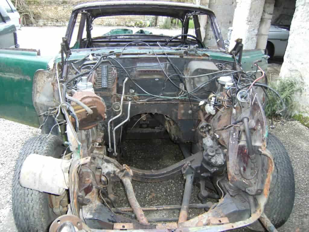
On the left as we look is the the vacuum reservoir, brake servo, and behind that is the washer bottle and then the fuse box. To the right and below the fusebox are the two aluminium pipes that take hot water to the rear heater.
As a comparison, here’s a view of a right-hand drive P5B’s engine compartment. Here the coil is on the left as this is probably a later car, but otherwise you can see the only differences are the steering gear being reversed, the location of the brake fluid reservoir and master cylinder, and the handbrake cable routing. This car also has the front heater and fan motor still in position on the bulkhead, but everything else is the same:

In the next photo of the front right wheel arch, you can see the splash panel behind the wheel. This encloses the door pillar area (A-pillar), which is a complex part of the car that features the pillar, box sections, front of the sill, and the scuttle. There is a lot to repair in this area if it’s very rusty.
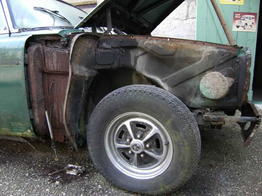
You can see the radio aerial dangling – the hole that the wire disappears through is also the hole that the front indicator repeater cables thread through, appearing in the front footwells behind the kick panels. Replacing these repeater units and re-routing the cables can be a frustrating experience on an assembled car. Normally the radio aerial is roof-mounted.
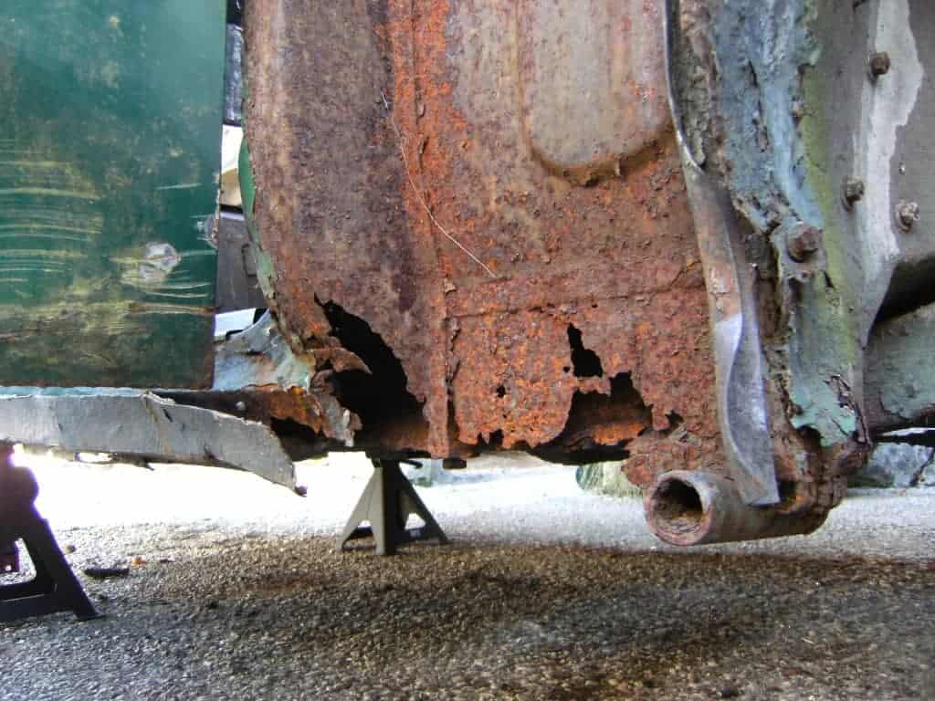
Here’s a close-up of the area behind the front wheel. This is the bottom of the area, and shows the extent of the rot. The tube in the lower-right is the jacking tube – I wouldn’t want to use the standard jack on this car! Note the bottom of the hinge pillar is severely rotten, as is the sill:
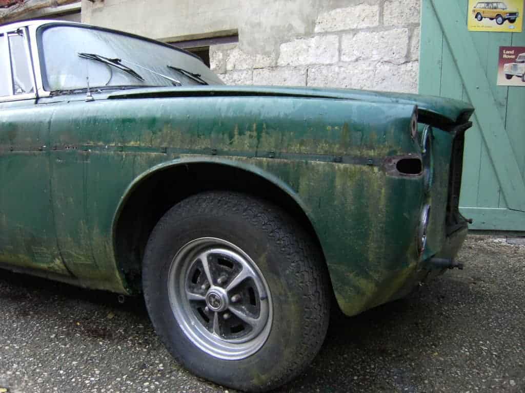
Here’s the inside of the front wing. As you can see, its rusty but not too bad – certainly re-usable after being cleaned-up. The area in the bottom-right of the photo is what was covering the corrosion in the previous photo – as mentioned before, P5’s are quite good at hiding rot beneath panels that look OK:
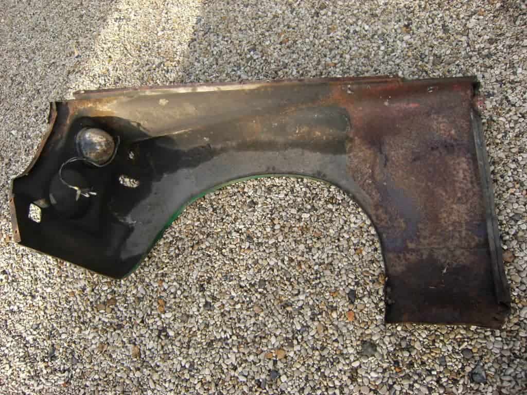
The front wing is actually formed of two panels that are welded (braised?) together – the front pressing for the lights is separately formed and there’s a seam running across then diagonally down and backwards to the wheel arch lip.
You can also see that this is a P5B wing, as it has the recess for the front fog lights that weren’t present on 3-litre cars:
Finally, here’s the front subframe removed from the car. This is a very substantial item, although it can rust, primarily along the bottom of the rear cross-member.

Starting at the left (rear) of the subframe and working right, we can see the bolts that mount the ends of the subframe – these mount approximately under the front seats, with the mounts on the ends of the subframe rails to control excess front-to-rear movement of the subframe.
Then we can see the torsion bar adjusters – it’s possible to vary the height of the front of the car slightly by adjusting these bolts that vary the ‘set’ of the torsion bars. The torsion bars are the two square-section tubes running forwards parallel to each other – these locate in the lower wishbones. They are each made of numerous torsion leaves.
On the upper face of the subframe we can also see two of the circular mounts that bolt to the body – these are isolated with rubber to insulate the body from noise and vibration. There are two more mounts at the front (not in view), making a total of 6 subframe mounts.
We can then see the front suspension and dampers, with the engine mounts just in-board of the dampers. Note also that the steering box is still mounted on the left of the subframe.
Although notionally a monocoque body, the P5 was something of a hybrid: the front featured this significant subframe, and the rear (as we shall see later) features ’chassis rails’ that are integral with the bodywork. Obviously this was the early days of monocoque construction, long before computer stress modelling, so the answer to uncertainty about managing stress was often to add more steel.
The next part will look at dismantling the engine. Stay tuned and Subscribe!